


PW : Polypropylene Capacitor: 160Vdc - 630Vdc
General purpose polypropylene axial wrap and end seal capacitors. Offering a wide range of capacitance and voltage alternatives. Ideal for applications as diverse as coupling, energy storage in SMPS.
Product description
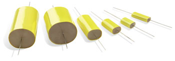
PW capacitors are constructed using the familiar wrap and end seal method - wrapping the wound elements with heavy duty electrical tape which is wider than the element and sealing the cavities formed at each end with epoxy resin. This style of manufacture results in a cost effective and volumetrically efficient component of the highest quality.
The components are ideal for a wide range of applications, particularly those requiring very low loss or dielectric absorption component such as sample and hold circuits.
If you have a specific requirement or query then please contact us, alternate capacitances, aspect ratios, lead outs are possible to meet specific requirements. Ripple current ratings for general filtering applications are available on request.

Technical details
| Capacitance range | 68nF to 100µF See size chart for details |
Temperature range | -55 to + 100°C |
| Tolerance | ± 10% standard. Others by request | Environmental category | 55/100/56 to EN60068 - 1 (IEC68-1) |
| Dissipation factor | ≤ 0.001 @ 1KHz & 20 ± 3°C | Proof voltage test | 1.5 x rated voltage for 30s. Not to be repeated |
| Insulation resistance | 104MΩ-µF (C>330nF), ≥ 3 x10⁴MΩ (C ≤ 330nF) @ rated voltage and 20 ± 3°C | Solderability | BS2011 : Part 2.1 T (IEC 68-2-20) Solder Globule Method of test Ta |
| Rated voltage | Polypropylene 160V, 250V 400V & 630Vdc | Vibration | EN60068 -2 - 6 (IEC68 -2 - 6) Test Fc 10 to 500 Hz 0.75mm or 98m/s2 |
| Pulse performance | See table. Ratings assume linear change to / from rated voltage | Bump | EN60068 - 2 - 29 (IEC 68 - 2 - 29) Test Eb 390m/s° 1000± 10 bumps |
Components
| Cap | Vac (Vrms) |
Vdc (V) |
dV/dt (V/µs) |
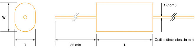
L (mm) |
W (mm) |
T (mm) |
t (mm) |
| 470nF | 110 | 160 | 20 | 20 | 11 | 6 | 0.8 |
| 680nF | 110 | 160 | 20 | 20 | 12 | 7.5 | 0.8 |
| 1.00µF | 110 | 160 | 20 | 20 | 14.5 | 10 | 0.8 |
| 1.50µF | 110 | 160 | 15 | 30 | 14 | 9.5 | 0.8 |
| 2.20µF | 110 | 160 | 15 | 30 | 16 | 11.5 | 0.8 |
| 3.30µF | 110 | 160 | 15 | 30 | 18.5 | 14 | 0.8 |
| 4.70µF | 110 | 160 | 10 | 34 | 19 | 14.5 | 0.8 |
| 6.80µF | 110 | 160 | 10 | 34 | 22.5 | 17.5 | 0.8 |
| 10.0µF | 110 | 160 | 10 | 34 | 26.5 | 22 | 0.8 |
| 15.0µF | 110 | 160 | 5 | 47 | 26 | 21.5 | 0.8 |
| 22.0µF | 110 | 160 | 5 | 47 | 31 | 26 | 0.8 |
| 33.0µF | 110 | 160 | 5 | 47 | 37.5 | 33 | 0.8 |
| 47.0µF | 110 | 160 | 5 | 47 | 44 | 39 | 0.8* |
| 68.0µF | 110 | 160 | 5 | 47 | 52 | 47 | 0.8* |
| 100.0µF | 110 | 160 | 5 | 47 | 62 | 57 | 0.8* |
| 150nF | 175 | 250 | 80 | 20 | 10 | 5 | 0.6 |
| 220nF | 175 | 250 | 80 | 20 | 11 | 6 | 0.6 |
| 330nF | 175 | 250 | 80 | 20 | 12.5 | 8 | 0.6 |
| 470nF | 175 | 250 | 80 | 20 | 15 | 10 | 0.8 |
| 680nF | 175 | 250 | 80 | 20 | 17 | 12.5 | 0.8 |
| 1.00µF | 175 | 250 | 50 | 30 | 16 | 11.5 | 0.8 |
| 1.50µF | 175 | 250 | 50 | 30 | 19 | 14 | 0.8 |
| 2.20µF | 175 | 250 | 50 | 30 | 22 | 17.5 | 0.8 |
| 3.30µF | 175 | 250 | 50 | 30 | 26.5 | 22 | 0.8 |
| 4.70µF | 175 | 250 | 35 | 34 | 27 | 22.5 | 0.8 |
| 6.80µF | 175 | 250 | 35 | 34 | 32 | 27 | 0.8 |
| 10.0µF | 175 | 250 | 12 | 47 | 31 | 26 | 0.8 |
| 15.0µF | 175 | 250 | 12 | 47 | 37 | 32 | 0.8 |
| 22.0µF | 175 | 250 | 12 | 47 | 44 | 39 | 0.8* |
| 22.0µF | 175 | 250 | 5 | 60 | 46 | 41 | 0.8* |
| 47.0µF | 175 | 250 | 5 | 60 | 54 | 49 | 0.8* |
| 100nF | 250 | 400 | 150 | 20 | 10 | 5.5 | 0.6 |
| 150nF | 250 | 400 | 150 | 20 | 11.5 | 7 | 0.6 |
| 220nF | 250 | 400 | 150 | 20 | 13.5 | 8.5 | 0.6 |
| 330nF | 250 | 400 | 150 | 20 | 16 | 11 | 0.6 |
| 470nF | 250 | 400 | 100 | 30 | 17 | 12.5 | 0.8 |
| 680nF | 250 | 400 | 150 | 20 | 10 | 5.5 | 0.6 |
| 1.00µF | 250 | 400 | 100 | 30 | 20 | 15 | 0.8 |
| 1.50µF | 250 | 400 | 100 | 30 | 23.5 | 19 | 0.8 |
| 2.20µF | 250 | 400 | 100 | 30 | 28 | 23.5 | 0.8 |
| 3.30µF | 250 | 400 | 50 | 34 | 29.5 | 25 | 0.8 |
| 4.70µF | 250 | 400 | 50 | 34 | 34.5 | 30 | 0.8 |
| 6.80µF | 250 | 400 | 20 | 47 | 33.5 | 28.5 | 0.8 |
| 10.0µF | 250 | 400 | 20 | 47 | 39.5 | 34.5 | 0.8 |
| 15.0µF | 250 | 400 | 20 | 47 | 47.5 | 42.5 | 0.8* |
| 22.0µF | 250 | 400 | 10 | 60 | 49 | 44 | 0.8* |
| 33.0µF | 250 | 400 | 10 | 60 | 59 | 54 | 0.8* |
| 68nF | 250 | 630 | 200 | 20 | 10.5 | 5.5 | 0.6 |
| 100nF | 250 | 630 | 200 | 20 | 11.5 | 6.5 | 0.6 |
| 150nF | 250 | 630 | 200 | 20 | 13.5 | 8.5 | 0.6 |
| 220nF | 250 | 630 | 150 | 30 | 12.5 | 8 | 0.6 |
| 330nF | 250 | 630 | 150 | 30 | 14.5 | 10 | 0.6 |
| 470nF | 250 | 630 | 150 | 30 | 16.5 | 12 | 0.8 |
| 680nF | 250 | 630 | 150 | 30 | 19.5 | 15 | 0.8 |
| 1.00µF | 250 | 630 | 60 | 34 | 20.5 | 15.5 | 0.8 |
| 1.50µF | 250 | 630 | 60 | 34 | 24 | 19.5 | 0.8 |
| 2.20µF | 250 | 630 | 60 | 34 | 28.5 | 24 | 0.8 |
| 3.30µF | 250 | 630 | 26 | 47 | 28 | 23 | 0.8 |
| 4.70µF | 250 | 630 | 26 | 47 | 33 | 28 | 0.8 |
| 6.80µF | 250 | 630 | 26 | 47 | 39 | 34 | 0.8 |
| 10.0µF | 250 | 630 | 26 | 47 | 46.5 | 41.5 | 0.8* |
* These components are available with tinned copper braid terminations for extra physical strength and current carrying capacity.
Maximum rates of change of Voltage dV/dt (V/µS)
Figures quoted in the chart above assume linear charge/discharge to / from rated voltage. When the applied voltage (VA) is less than the rated voltage (VR) the rating may be increased by a factor VR/VA-
Dimensions
Ordering details
| F | C | T | V |
| PW | 100n | K | 160V |
| PW | 2u2 | G | 630V |
F - Family: PW
C - Cap value n for C<1000nF, u for C≥1µF
T - Tolerance M=±20% K=±10% J=±5% G=±2%♪ F=±1%
V - Rated Voltage dc : 160, 250, 400, 630