


PCS : Polypropylene Capacitor: 700Vdc - 1800Vdc
Product description
The PCS range of capacitors has been designed to offer electronic circuit designers of dc filtering applications an alternative to electrolytic capacitors. Manufactured from a special metallised polypropylene film, the component offers a very high volumetric efficiency along with very low losses and high current handling capability.
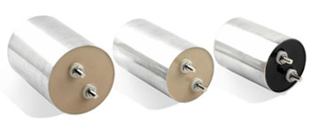
The design has particularly good self healing capabilities and is able to with stand high overvoltage stresses without becoming short circuit. The capacitors are housed in aluminium cans, with screw terminals or flying leads. Base mounting studs are available if required.

Components
Capacitance values in µF
| Size Code |
Rated operating voltage Vr / (Vdc) | ||||
| 700 | 900 | 1100 | 1400 | 1800 | |
| A | 42 | 28 | 15 | ||
| B | 73 | 47 | 30 | ||
| C | 110 | 70 | 50 | 25 | 15 |
| D | 84 | 56 | 35 | 20 | 10 |
| E | 146 | 94 | 60 | 35 | 25 |
| F | 220 | 140 | 100 | 55 | 35 |
| G | 130 | 84 | 50 | 30 | 20 |
| H | 220 | 144 | 95 | 55 | 35 |
| I | 330 | 220 | 150 | 80 | 55 |
| J | 424 | 270 | 190 | 110 | 70 |
| K | 430 | 280 | 190 | 110 | 70 |
| L | 540 | 350 | 240 | 140 | 90 |
| M | 620 | 400 | 280 | 160 | 105 |
| N | 520 | 340 | 240 | 140 | 90 |
| O | 660 | 430 | 310 | 175 | 115 |
| P | 760 | 500 | 360 | 205 | 135 |
| Q | 720 | 460 | 300 | 170 | 115 |
| R | 900 | 580 | 385 | 220 | 145 |
| S | 1040 | 680 | 445 | 255 | 170 |
Size codes
| Size Code |
D / mm (± 0.1) |
L / mm (± 0.1) |
| A | 50.0 | 70 |
| B | 63.5 | 70 |
| C | 76.0 | 70 |
| D | 50.0 | 110 |
| E | 63.5 | 110 |
| F | 76.0 | 110 |
| G | 50.0 | 145 |
| H | 63.5 | 145 |
| I | 76.0 | 145 |
| J | 84.4 | 145 |
| K | 76.0 | 165 |
| L | 84.4 | 165 |
| M | 90.0 | 165 |
| N | 76.0 | 185 |
| O | 84.4 | 185 |
| P | 90.0 | 185 |
| Q | 76.0 | 235 |
| R | 84.4 | 235 |
| S | 90.0 | 235 |
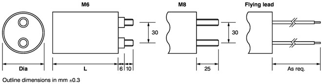
Dimensions
Expected life

Quality and useful life
The specification of quality data - which always refers to a fairly large number of components - does not constitute a guarantee of characteristics or properties in the legal sense. However, agreement on the specifications does not mean that the customer may not claim for replacement of individual defective components within the terms of delivery. We cannot, however, assume any further liability beyond the replacement of defective components. This applies in particular to any further consequences of component failure.
Furthermore, it must be taken into consideration that the figures stated for useful life and failure rate refer to the average production status and are therefore to be understood as mean values (statistical expectations) for a large number of delivery lots of identical capacitors. These figures are based on application experience and data obtained from preceding tests under normal conditions, or - for purposes of accelerated aging - more severe conditions.
Ordering details
| F | C | T | V | S | W |
| PCS | 190 | K | 1100 | J | M6 |
F - Family: PCS
C - Cap value n for C<1000nF, u for C≥1µF
T - Tolerance M=±20% K=±10% J=±5% G=±2% F=±1%
V - Rated Voltage dc : 700, 900, 1100, 1400, 1800
S - Size Code: A,B,C,D,E,F,G,H,I,J,K,L,M,N,O,P,Q,R,S
W - Terminals: M6, M8, FL (Flying Lead)